Bio-Decontaminate Your Space
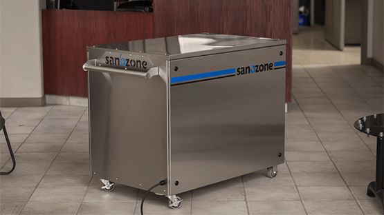
Introducing SANOZONE: Chemical-Free Pathogen Eradication 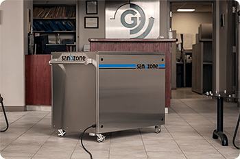
The SANOZONE system is a chemical-free, bio-decontamination unit to eradicate viruses, bacteria and other pathogens on every surface in response to the current COVID-19 pandemic.
Sectors
Industrial
In Situ / on Site Wastewater & Remediation Technologies for the Industrial Sector
Learn MoreProducts
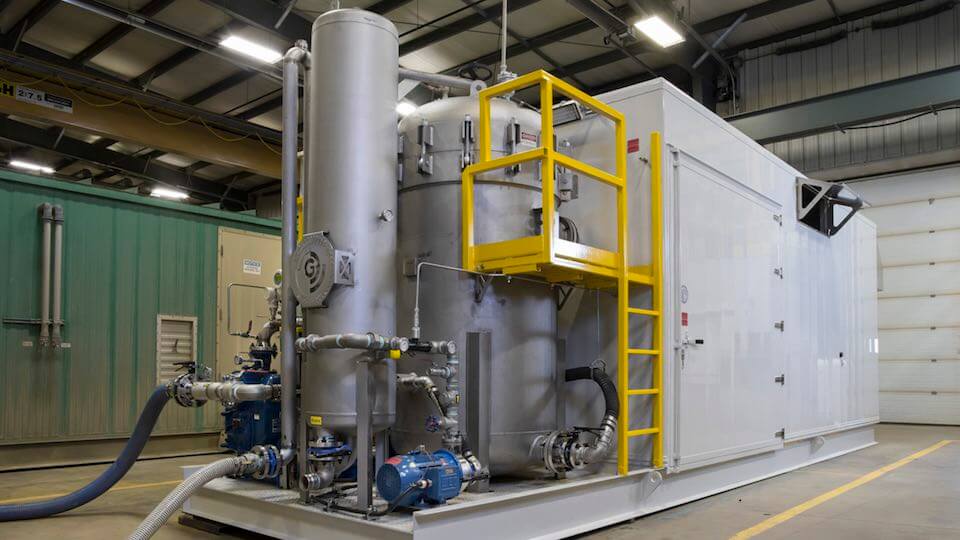
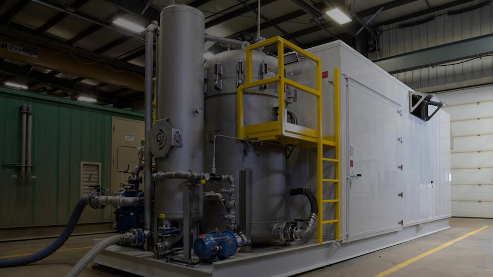
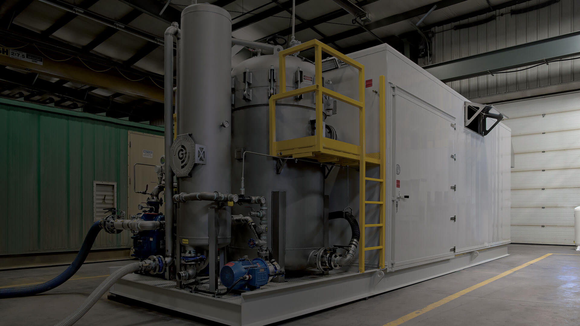
Electrocatalytic Oxidation System
Powerful, Chemical-Free Wastewater Treatment
A GEE-patented technology, the Electrocatalytic Oxidation (EOX) treatment system is a chemical-free, turnkey wastewater treatment process for oil and gas, municipal, industrial and agricultural industries. The EOX combines high current electrocoagulation with high concentration ozone to create the most powerful advanced electrocatalyitic oxidation approach found anywhere. Mobile, modular or fixed plant, the EOX achieves broad-spectrum contaminant removal without the use of chemicals.
News
Introducing SANOZONE Bio-Decontamination of Novel Coronavirus
28-May-2020 at 6:30 AM
SANOZONE Technologies in conjunction with Ground Effects Environmental and Geosyntec Consulting has developed an automated, chemical-free process for eradicating viruses and bacteria from all surfaces within large and complex spaces with minimal labour and no chemical residue.